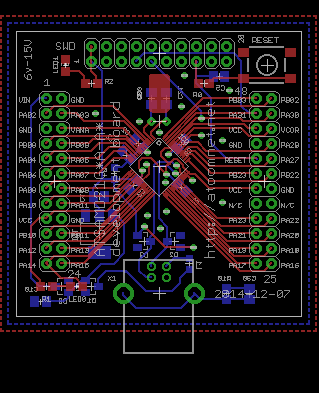
PCB to breakout a ATSAMD21 microcontroller.
ATSAMD21-board
A bare-bones ATSAMD21 breakout from 2014. The SAMD21G sits on a PCB with a USB-B connector, an SWD header, a 3.3V regulator and a 32.768kHz crystal, with two 2x12 sockets breaking out every pin.
What's on the board
- A SAMD21G.
- A USB-B connector.
- An SWD 2x10 header.
- An AMS1117-3.3 LDO.
- A 32.768kHz crystal.
- Red and green LEDs.
- Two 2x12 pin sockets (jp1, jp2).
The bring-up
5V from USB feeds the AMS1117-3.3, which makes the 3.3V rail for the SAMD21. The 32.768kHz crystal drives the RTC, and the SWD header lets you flash and debug the chip. All remaining pins appear on the two 2x12 sockets. I used pin sockets so the board can drop onto a carrier.