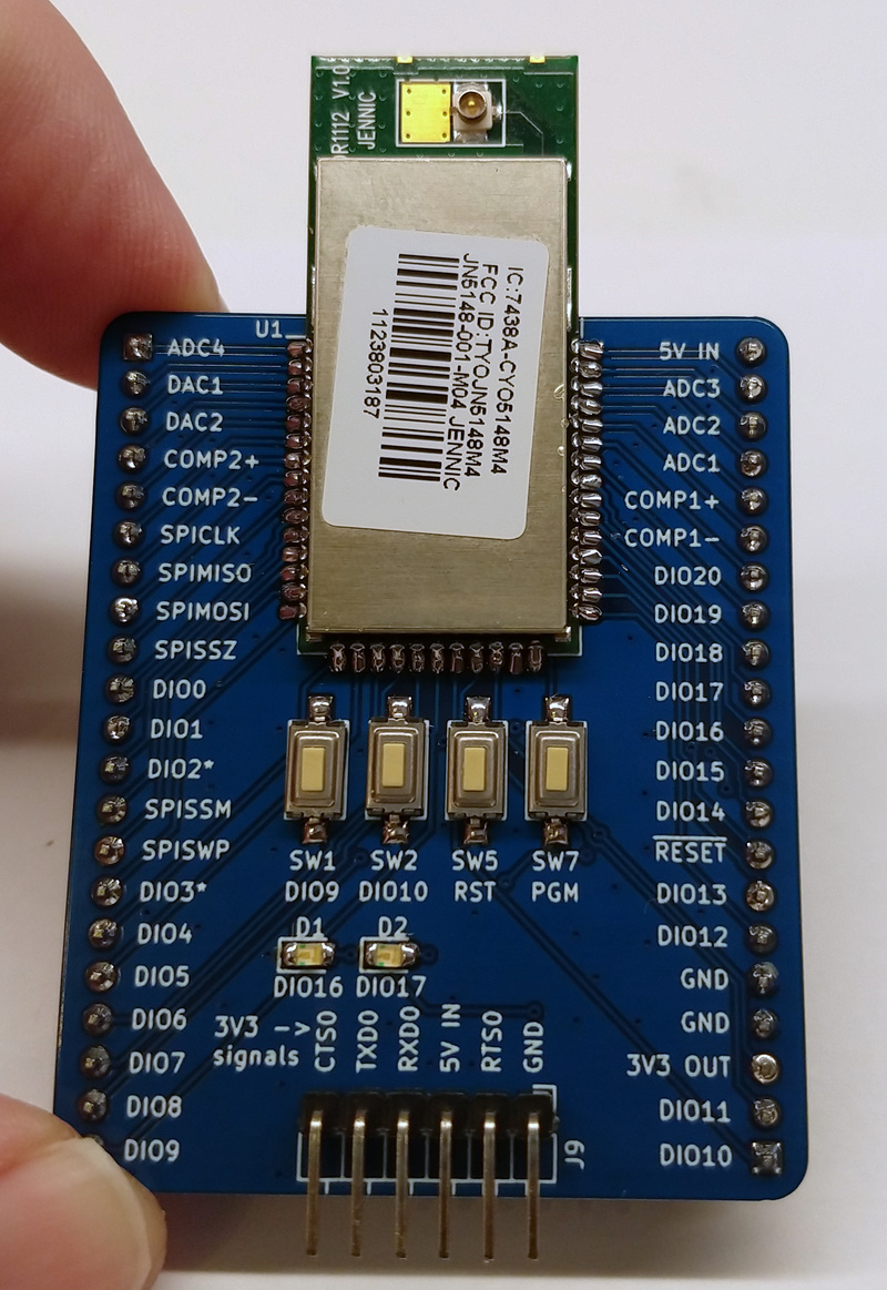
Jennic JN5148-001-M04 IEEE802.15.4 module breakout pcb.
Jennic-JN5148-001-M04 Breakout
The JN5148-001-M04 is a 32-bit NXP MCU with a built-in IEEE 802.15.4 radio. NXP killed the product line and scrubbed almost every document from their site. This breakout board keeps the module alive, bringing every pin out to 2.54 mm headers so you can actually prototype with it again.
What's on the board
- The JN5148-001-M04 module, hand-solder footprint
- An AMS1117-3.3 regulator bringing 5 V down to 3.3 V
- Reset and program (PGM) buttons
- 2.54 mm headers: a 21-pin row on each side plus a 6-pin programming header
- Solder jumpers to strap SPI flash config
The board does the housekeeping so the module just works. 5 V in becomes 3.3 V on the AMS1117. Hold PGM and tap RST to reach programming mode, then use a 3.3 V serial adapter with the NXP JN51xx Flash Programmer to flash and confirm the MAC address.